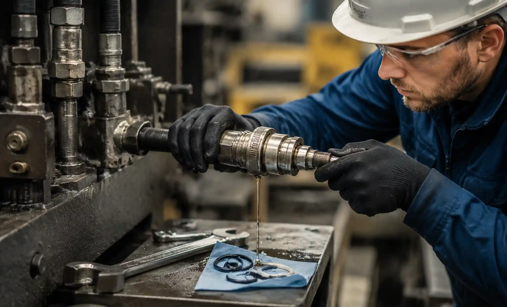




Cómo prevenir fugas en conexiones de acoplamiento rápido
Los sistemas de acoplamiento rápido sufren fugas en operaciones industriales debido al desgaste de juntas tóricas, una instalación incorrecta, picos de presión y contaminación. Los datos del sector muestran que las fallas de acoplamiento representan aproximadamente el 25-30% del tiempo de inactividad no planificado en sistemas hidráulicos y de transferencia de fluidos, con problemas relacionados con fugas que costan a las instalaciones miles de dólares anuales en fluidos desperdiciados, daños en equipos y pérdidas de producción.
Si quieres evitar fugas en tus conexiones de acoplamiento rápido, tendrás que entender las causas principales de los fallos de sello, las técnicas adecuadas de instalación, los calendarios de mantenimiento y los criterios de selección de materiales para tu aplicación específica.
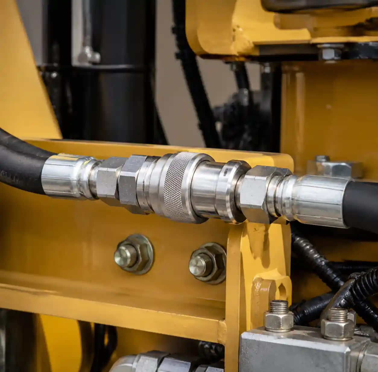
! 1-conexión-rápida-sistema-industrial Conexión de acoplamiento rápido instalada en un sistema industrial de transferencia de fluidos
- 1. Entendiendo los mecanismos de fugas de acoplamiento rápido
- 2. Causas principales de fugas rápidas de acoplamiento
- 2.1. Juntas tóricas desgastadas o dañadas
- 2.2. Técnicas de instalación incorrectas
- 2.3. Picos y subidas de presión
- 2.4. Contaminación y escombros
- 3. Métodos probados de prevención de fugas
- 3.1. Selecciona el material de acoplamiento adecuado para tu aplicación
- 3.2. Implementar procedimientos adecuados de instalación
- 3.3. Establecer calendarios de mantenimiento regulares
- 3.4. Presión y dinámica del flujo del sistema de control
- 3.5. Proteger las conexiones de la contaminación
- 4. Tecnologías avanzadas de sellado para aplicaciones críticas
- 5. Errores comunes en la instalación y cómo evitarlos
- 6. Consideraciones de compatibilidad de materiales
- 7. Solucionando fugas de acoplamiento existentes
- 8. Preguntas frecuentes
- 8.1. ¿Con qué frecuencia debería cambiar las juntas tóricas en los acoplamientos rápidos?
- 8.2. ¿Puedo mezclar marcas de acoplamiento o usar componentes de diferentes fabricantes?
- 8.3. ¿Qué presión debo usar para la prueba de fugas después de la instalación del acoplamiento?
- 8.4. ¿Por qué mis acoplamientos solo gotean cuando están fríos pero sellan bien cuando están calientes?
- 8.5. ¿Cómo evito fugas al conectar los acoplamientos bajo presión residual del sistema?
- 8.6. ¿Qué causa fugas de acoplamiento solo a caudales altos pero no a bajos caudales?
- 9. Conclusión
Entendiendo los mecanismos de fugas de acoplamiento rápido
Los acoplamientos rápidos son dispositivos de conexión diseñados con precisión que permiten la fijación y desprendimiento rápidos de líneas de fluido sin necesidad de herramientas. Estos accesorios dependen de elementos de sellado internos—principalmente juntas tóricas y sellos frontales—para mantener un funcionamiento sin fugas bajo presión.
El mecanismo de sellado funciona mediante compresión. Cuando conectas las mitades de acoplamiento macho y hembra, la junta tórica interna se comprime contra ambas superficies metálicas, creando un sello activado por presión que se vuelve más apretado a medida que aumenta la presión del sistema. Este diseño proporciona un rendimiento fiable a través de presiones de funcionamiento desde 30 psi hasta más de 10.000 psi, dependiendo del tipo de acoplamiento y la construcción.
Sin embargo, este sistema de sellado es vulnerable a varios modos de fallo que comprometen el rendimiento y provocan fugas.
Causas principales de fugas rápidas de acoplamiento
Juntas tóricas desgastadas o dañadas
La degradación de los juntas tóricas es la principal causa de fugas rápidas en el acoplamiento, representando aproximadamente el 60-70% de todas las fallas de acoplamiento. Estos sellos elastoméricos se deterioran mediante múltiples mecanismos, incluyendo el ajuste de compresión, el ataque químico, el ciclo térmico y la abrasion.
El conjunto de compresión ocurre cuando los anillos tóricos permanecen bajo presión constante durante largos periodos. El elastómero pierde su capacidad de volver a su forma original, reduciendo la fuerza de sellado y permitiendo que el fluido se escape. Las juntas tóricas estándar de nitrilo experimentan una compresión medible, establecida tras 1000-2000 horas de uso continuo a temperaturas elevadas superiores a 80°C.
La incompatibilidad química acelera la falla de la junta tórica. Cuando los materiales de acoplamiento entran en contacto con fluidos incompatibles, el elastómero se hincha, agrieta o endurece. Por ejemplo, los anillos Tóricos de nitrilo se hinchan rápidamente en hidrocarburos aromáticos y cetonas, mientras que los sellos EPDM se degradan en aceites derivados del petróleo.
Técnicas de instalación incorrectas
Los errores de instalación generan fugas inmediatas o aceleran el desgaste. Los errores comunes incluyen el enhebrado cruzado, inserciones incompletas, desalineación angular y carga lateral excesiva durante la conexión.
La inserción incompleta es especialmente problemática. Cuando las mitades de acoplamiento no se acoplan completamente, el mecanismo de bloqueo no comprime adecuadamente la junta tórica. Puedes identificar esta condición comprobando que la manga de acoplamiento se bloquee completamente y que no haya espacio entre las superficies de acoplamiento.
Una desalineación angular superior a 3-5 grados provoca compresión desigual del anillo tórico y puntos de esfuerzo concentrados. Esta desalineación suele deberse a tuberías rígidas que obligan a los acoplamientos a posiciones no axiales, creando caminos de fuga preferentes en un lado del sello.
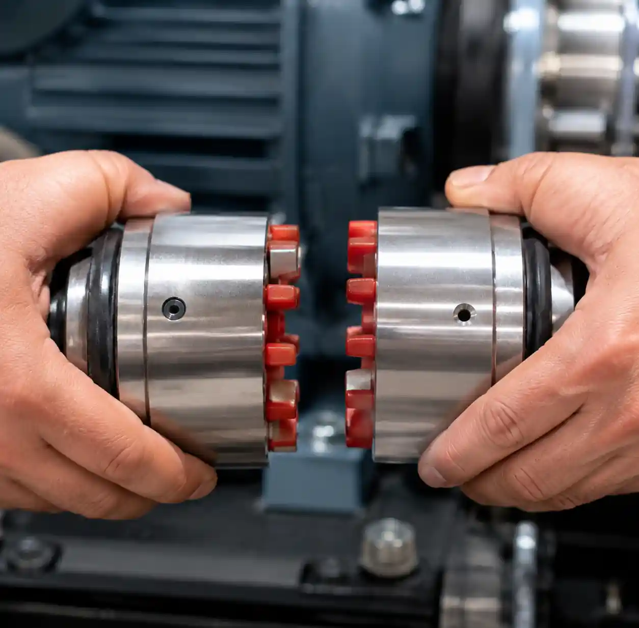
! 3-acoplamiento-instalación-alineación-técnica Técnica adecuada de alineación axial para la instalación rápida de acoplamientos
Picos y subidas de presión
Los eventos de choque hidráulico generan picos de presión que pueden superar los límites de acoplamiento en un 200-400%. Estos eventos de presión transitoria obligan a los anillos tóricos a separarse entre los componentes metálicos, causando daños por extrusión y deformación permanente.
El golpe de ariete en sistemas líquidos y las sobretensiones en aplicaciones neumáticas generan estos eventos dañinos. Un cierre repentino de la válvula puede generar ondas de presión que viajan a 1000-1500 m/s, produciendo presiones instantáneas de 5 a 10 veces superiores a la presión normal de operación.
Deberías instalar supresores de sobretensiones y válvulas de alivio de presión cuando la dinámica del sistema incluya cambios direccionales rápidos, válvulas de acción rápida o ciclos de arranque-parada de la bomba que generen transitorios de presión.
Contaminación y escombros
La contaminación por partículas es la segunda causa más común de fugas en el acoplamiento. El material extraño en las caras de acoplamiento impide un sellado adecuado, mientras que las partículas abrasivas incrustadas en juntas tóricas crean canales de fuga y aceleran el desgaste.
La suciedad, partículas metálicas, óxido y restos del proceso entran en los acoplamientos durante la conexión si no limpias primero las superficies de acoplamiento. Incluso partículas microscópicas de 10-50 micras pueden comprometer la integridad del sellado al crear huecos entre la junta tórica y la superficie de asiento.
La contaminación entra por tres vías principales: superficies de conexión sucias, fluidos contaminados circulando por el sistema y exposición ambiental cuando los acoplamientos permanecen sin tapar entre usos.
Métodos probados de prevención de fugas
Selecciona el material de acoplamiento adecuado para tu aplicación
La selección del material afecta directamente a la longevidad del sellado y a la prevención de fugas. Debes adaptar el material del cuerpo de acoplamiento y el elastómero del anillo tórico a tus requisitos específicos de fluido, rango de temperatura y presión.
Para aplicaciones de aceite hidráulico que operan a temperaturas de -20°C a 100°C, los acoplamientos de acero inoxidable 316 con juntas tóricas de nitrilo (NBR) ofrecen un rendimiento excelente. La carrocería resistente a la corrosión resiste ambientes hostiles, mientras que los sellos NBR mantienen la flexibilidad y la fuerza de sellado en este rango de temperaturas.
El procesamiento químico requiere materiales más especializados. Los acoplamientos revestidos de PTFE con juntas tóricas Viton o FFKM manejan productos químicos, ácidos y disolventes agresivos que destruirían los sellos estándar de nitrilo en cuestión de horas. Estos materiales cuestan entre 3 y 5 veces más que los componentes estándar, pero eliminan fallos por fugas en el servicio corrosivo.
Las aplicaciones a altas temperaturas por encima de 150°C requieren sellos metálicos de PTFE con sello en C o PTFE energizado por muelle que mantengan la fuerza de sellado cuando los elastómeros fallarían. Estos diseños permiten un funcionamiento sin fugas hasta 300°C en aplicaciones de vapor, aceite térmico y gas caliente.
| Aplicación | Material del cuerpo | Material del anillo tórico | Rango de temperatura | Clasificación de presión |
|---|---|---|---|---|
| Aceite hidráulico | Acero inoxidable 316 | Nitrilo (NBR) | -20°C a 100°C | 0-350 bar |
| Sistemas de agua | Latón, SS304 | EPDM | 0°C a 80°C | 0-16 compás |
| Transferencia química | SS316, Hastelloy | Viton (FKM) | -15°C a 150°C | 0-250 bar |
| Vapor a Altas Temperaturas | SS316, Acero al Carbono | FFKM, Metal C-Seal | Hasta 300°C | 0-100 bar |
| Aire neumático | Latón, aluminio | NBR, Poliuretano | -10°C a 80°C | 0-15 compás |
Implementar procedimientos adecuados de instalación
La técnica de instalación correcta previene entre el 80 y el 90% de fallos inmediatos de acoplamiento. Debes seguir estos procedimientos verificados para cada conexión:
Inspección previa a la conexión: Examinar ambas mitades de acoplamiento en busca de daños visibles, comprobando el estado de la junta tórica, las superficies de sellado y los mecanismos de bloqueo. Sustituye cualquier acoplamiento que muestre grietas, surcos o componentes desgastados antes de la instalación.
Limpieza de superficies: Limpia todas las superficies de acoplamiento con un paño sin pelusa y disolvente aprobado para eliminar partículas, aceites y residuos. Este paso es fundamental: incluso una fina película de contaminación puede causar fugas inmediatas.
Lubricación: Aplicar una fina película de lubricante compatible con el sistema sobre juntas tóricas y superficies de sellado. Esto reduce la fuerza de inserción, evita el rodamiento o torsión del anillo tórico y extiende la vida útil del sellado al reducir la fricción durante la conexión. Utiliza solo lubricantes compatibles tanto con el material de la junta tórica como con el fluido de proceso.
Alineación axial: Asegúrese de que las mitades de acoplamiento se alineen dentro de 3 grados de la línea central axial antes de la conexión. Soporte mangueras o tuberías para eliminar cargas laterales que tensionen los sellos y causen fallos prematuros.
Acoplamiento completo: Empuja firmemente las mitades de acoplamiento hasta que el mecanismo de bloqueo se active con un clic audible. Verifica que no haya ningún hueco entre los cuerpos de acoplamiento y que la manga de bloqueo cubra completamente el punto de conexión.
Prueba de presión: Tras la conexión, presurizar el sistema gradualmente hasta el 50% de la presión de funcionamiento e inspeccionar si hay fugas. Mantén esta presión durante 2-3 minutos antes de aumentar hasta la máxima presión de funcionamiento.
Establecer calendarios de mantenimiento regulares
El mantenimiento preventivo detecta la degradación del sellado antes de que se desarrollen fugas. Debes implementar intervalos de inspección basados en la gravedad del operación:
Aplicaciones industriales estándar: Inspeccionar los acoplamientos cada 3 meses (aproximadamente 2000 horas de funcionamiento). Comprobar si hay fugas externas, verificar el funcionamiento del mecanismo de bloqueo y cambiar las juntas tóricas anualmente, independientemente de la condición visible.
Entorno Duro o Operaciones de Alto Ciclo: Inspeccionar mensualmente (500 horas de funcionamiento). Estas aplicaciones incluyen hidráulica móvil, servicios a altas temperaturas por encima de 100°C o sistemas con ciclos frecuentes de conexión-desconexión que superan las 10 veces al día.
Aplicaciones críticas: Implementar protocolos de inspección semanales para sistemas donde las fugas puedan causar riesgos para la seguridad, contaminación ambiental o costosas pérdidas de producción. Las operaciones de procesamiento de alimentos, fabricación farmacéutica y manipulación de productos químicos suelen requerir esta frecuencia.
Durante la inspección, mide el diámetro de la sección transversal del anillo tórico con pinzas. Sustituye las juntas tóricas que presenten una reducción superior al 10% en la sección transversal o cualquier grieta, endurecimiento o deterioro superficial visible.
Presión y dinámica del flujo del sistema de control
La gestión de la presión protege los sellos de eventos de estrés dañinos. Puedes implementar estos controles de ingeniería para eliminar fallos inducidos por la presión:
Supresores de sobretensiones: Instalar acumuladores hidráulicos o tanques neumáticos de sobretensión cerca de los acoplamientos que experimentan picos de presión. Estos dispositivos absorben las ondas de presión antes de alcanzar los sellos de acoplamiento, reduciendo las presiones máximas en un 60-80%.
Válvulas de alivio de presión: Ajusta las válvulas de alivio para que se abran al 110-120% de la presión máxima de funcionamiento. Esto proporciona margen de seguridad y evita eventos de presión extremos que extruyen juntas tóricas en huecos de espacio.
Limitación de caudal: Tamaño de los acoplamientos según los requisitos reales de flujo en lugar del diámetro máximo de la tubería. Los acoplamientos sobredimensionados generan turbulencias y caídas de presión que esfuerzan los sellos, mientras que las conexiones de tamaño adecuado mantienen el flujo laminar y una presión estable.
Presurización gradual: Tren a los operadores para abrir las válvulas lentamente, llevando los sistemas a presión de funcionamiento durante 30-60 segundos en lugar de instantáneamente. Esto elimina el golpe de ariete y permite que los sellos se compriman gradualmente bajo carga.
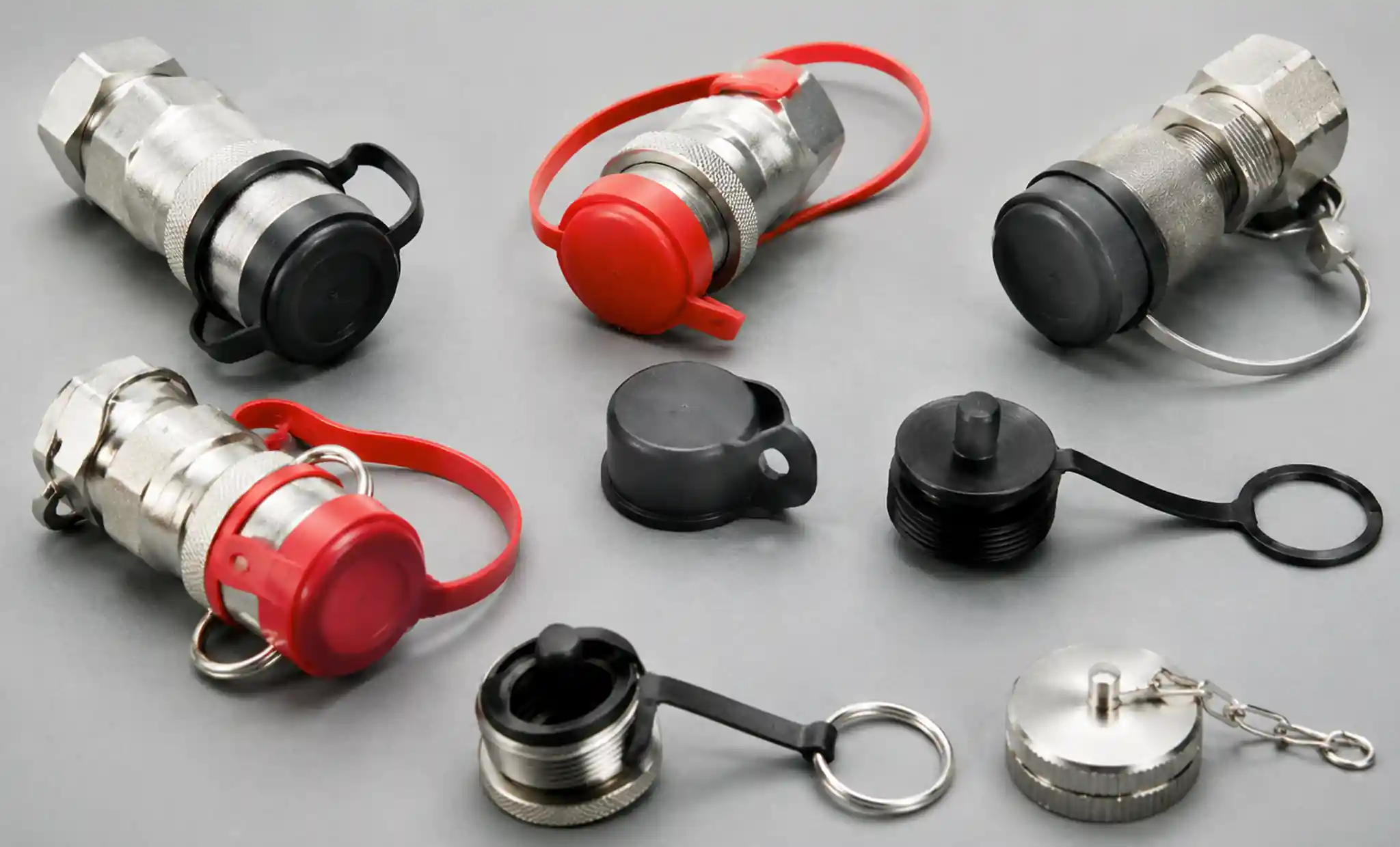
! 6-acoplamiento-capuches-polvo-protección-contaminación Tapas antipolvo de acoplamiento rápido y cubiertas protectoras para la prevención de contaminaciones
Proteger las conexiones de la contaminación
El control de contaminación requiere tanto disciplina procedimental como barreras físicas. Debes implementar estos métodos de protección:
Tapas y enchufes antipolvo: Tapa todas las mitades de acoplamiento desconectadas inmediatamente después de separarse. Guarda los acoplamientos de repuesto con tapas protectoras instaladas para evitar la entrada de partículas durante el almacenamiento. Esta práctica sencilla elimina el 90% de los fallos relacionados con la contaminación.
Protocolo de Limpieza Pre-Conexión: Establecer procedimientos de limpieza obligatorios que requieran a los operadores limpiar las caras de acoplamiento con un paño limpio antes de cada conexión. Proporciona estaciones de limpieza con disolventes aprobados y toallitas sin pelusa en los puntos de acoplamiento.
Filtración de fluidos: Instalar filtros en línea aguas arriba de las conexiones de acoplamiento, dimensionados para capturar partículas de hasta 25 micras. Esto protege los sellos de la contaminación que circula por el sistema. Cambia los elementos filtrantes antes de que la diferencia de presión supere las especificaciones del fabricante.
Protección ambiental: Utiliza botas o fundas protectoras en los acoplamientos expuestos a ambientes hostiles, incluyendo polvo, humedad y salpicaduras químicas. Estas cubiertas flexibles protegen la zona de conexión y permiten el funcionamiento por acoplamiento.
Tecnologías avanzadas de sellado para aplicaciones críticas
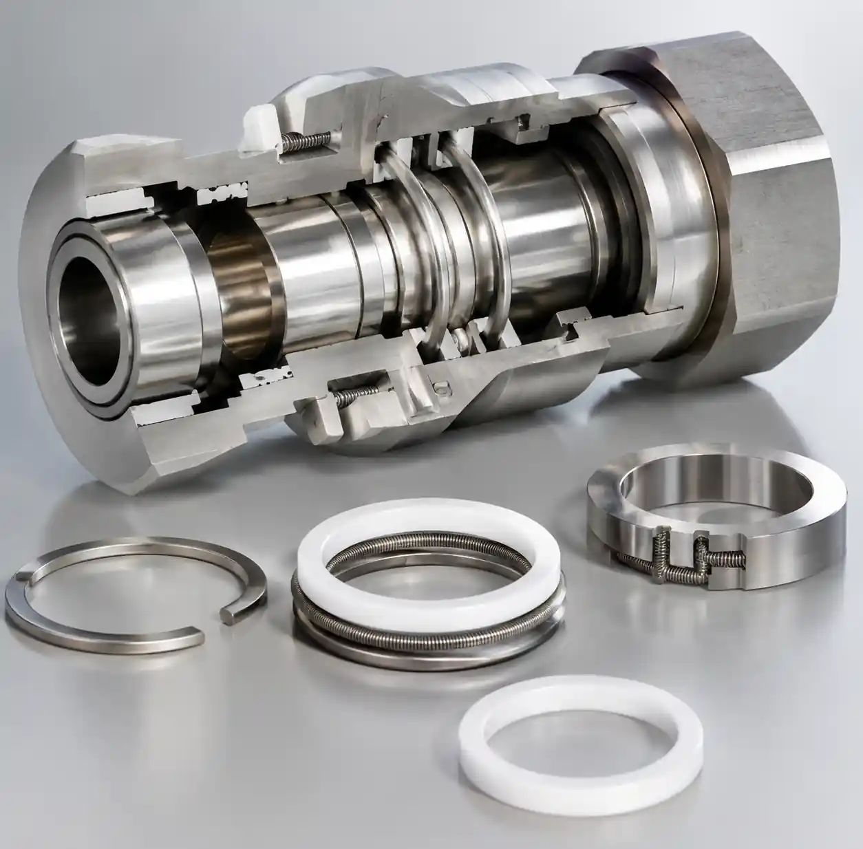
! 7-tecnología-sello-avanzada-metal-c-seal Tecnologías avanzadas de sello metálico en C y PTFE energizado por muelle para acoplamientos rápidos
Los diseños modernos de acoplamiento incorporan tecnologías de sellado mejoradas que reducen el riesgo de fugas en aplicaciones exigentes. Puedes especificar estas características avanzadas cuando los sellos estándar de juntas tóricas no cumplen con los requisitos de rendimiento:
Sellos metálicos en C: Los sellos metálicos con resorte proporcionan un rendimiento hermético en aplicaciones a altas temperaturas por encima de 200°C donde fallan los elastómeros. Estos sellos mantienen la fuerza de sellado mediante ciclos térmicos y fluctuaciones de presión, lo que los hace ideales para el servicio de vapor, aceite caliente y gas a alta temperatura.
Sellos de PTFE energizados por muelle: Combinando la resistencia química del PTFE con la fuerza de sellado con resorte, estos diseños manejan productos químicos agresivos y amplios rangos de temperatura desde -200°C hasta 260°C. El muelle mantiene una carga constante en la cara del sello independientemente de las fluctuaciones de presión o la expansión térmica.
Diseños de Doble Sello: Los elementos de sellado redundantes proporcionan protección de respaldo si falla el sello principal. Estos acoplamientos cuentan con dos juntas tóricas independientes o una combinación de junta tórica y sello frontal, reduciendo la probabilidad de fuga en un 95% en comparación con los diseños de un solo sello.
Acoplamientos de sellado frontal: Los sellos metálicos con respaldo resistente al fuego eliminan por completo los elastómeros para servicios extremos, incluyendo fluidos criogénicos, ambientes de alta radiación y aplicaciones de ultra-alto vacío hasta 10⁻⁹ mbar.
Errores comunes en la instalación y cómo evitarlos
| Error de instalación | Consecuencia | Método de prevención | Método de detección |
|---|---|---|---|
| Hilos cruzados | Roscas dañadas, sello incompleto | Aprieta a mano las primeras 2-3 vueltas, verifica la rotación suave | Resistencia durante el roscado, caras de acoplamiento desalineadas |
| Inserción incompleta | Compresión parcial del anillo tórico, fugas inmediatas | Empuja hasta que se escuche un clic, verifica que no haya espacio | Comprobación visual, medición de la profundidad de inserción |
| Instalación de juntas tóricas secas | Daño en la junta tórica durante la conexión, fallo temprano | Aplicar lubricante compatible con el sistema | Se requiere una fuerza de inserción excesiva |
| Superficies contaminadas | Las partículas impiden el sellado | Limpia ambas caras con un paño limpio antes de conectar | Residuos o residuos visibles en las caras de acoplamiento |
| Desalineación angular | Compresión desigual de sello, concentración de esfuerzos | Mangueras de soporte, alinear dentro de 3° antes de la conexión | Cuerpos de acoplamiento no paralelos, desplazamiento angular visible |
| Carga lateral excesiva | Deformación del sello, desgaste prematuro | Utiliza acoplamientos giratorios o mangueras flexibles | Acoplamiento tirado en ángulo desde la posición natural |
| Sobrepresurización | Extrusión del anillo tórico, daño permanente | Instalar válvulas de alivio, rampa de control de presión | Lecturas del manómetro por encima del límite de diseño |
Consideraciones de compatibilidad de materiales
La compatibilidad química entre juntas tóricas y fluidos de proceso determina la longevidad del sello. Debes verificar la compatibilidad antes de seleccionar materiales de acoplamiento para evitar una rápida degradación y fugas de sellado.
Nitrilo (NBR): Excelente para el servicio de aceites petrolíferos, agua y aire desde -40°C hasta 100°C. El NBR se hincha rápidamente en cetonas, ésteres e hidrocarburos aromáticos. Úsalo para aplicaciones hidráulicas y neumáticas generales.
Viton (FKM): Resistencia química superior a ácidos, disolventes, combustibles y aceites con capacidad de temperatura de hasta 200°C. No es compatible con cetonas, aminas y ésteres de bajo peso molecular. Especifica para procesamiento químico y hidráulica de alta temperatura.
EPDM: Ideal para agua, vapor y fluidos a base de glicol hasta 150°C. Se degrada en aceites petrolíferos y disolventes hidrocarburos. Uso en sistemas de agua caliente, servicio de vapor y líquidos de frenos.
FFKM (Perfluoroelastómero): Resistencia química universal que incluye ácidos agresivos, cáusticos, disolventes y oxidantes. Rango de temperatura de -15°C a 325°C. El coste es entre 10 y 20 veces superior al del NBR, pero elimina las preocupaciones sobre la compatibilidad química.
PTFE (Politetrafluoroetileno): Inerte para prácticamente todos los productos químicos industriales con uso continuo hasta 260°C. Requiere energizador de muelle para la fuerza de sellado. Especifica para servicios químicos extremos y aplicaciones de ultra-alta pureza.
Puedes consultar las tablas de compatibilidad química de fabricantes de sellos para verificar el rendimiento del material de los anillos tóricos con fluidos específicos. Estos recursos proporcionan datos detallados de crecimiento, límites de temperatura y tasas de degradación para miles de combinaciones químicas.
Solucionando fugas de acoplamiento existentes
Cuando se producen fugas en los acoplamientos instalados, el diagnóstico sistemático identifica las causas raíz y previene la recurrencia. Sigue esta secuencia de resolución de problemas:
Paso 1 - Despresurizar y Desconectar: Liberar toda la presión del sistema antes de inspeccionar el acoplamiento. Desconecta las mitades de acoplamiento y examina ambos lados por separado.
Paso 2 - Inspeccionar las juntas tóricas: Quitar las juntas tóricas y medir el diámetro de la sección transversal con pinzas. Compáralo con las nuevas dimensiones de la junta tórica. Sustituye si la sección transversal se reduce en más del 10%, o si observas grietas, endurecimiento o irregularidades superficiales.
Paso 3 - Comprobar las superficies de sellado: Examina las superficies metálicas de sellado con aumento para detectar arañazos, surcos o picaduras por corrosión. Defectos superficiales menores de 0,1 mm pueden pulirse a menudo con tela abrasiva de grano 600. El daño profundo requiere reemplazo de acoplamiento.
Paso 4 - Verificar el mecanismo de bloqueo: Comprobar que las mangas, bolas o pasadores de bloqueo encaje completamente y se sujete firmemente. Los componentes de bloqueo desgastados permiten acoplar la separación bajo presión, causando fugas catastróficas.
Paso 5 - Limpiar y volver a montar: Limpiar todos los componentes a fondo, instalar juntas tóricas nuevas con lubricación adecuada, volver a conectar con la alineación correcta y hacer prueba de presión antes de volver al servicio.
! 9-acoplamiento-fuga-proceso-diagnóstico Técnico en resolución de problemas y reparación de conexiones de acoplamiento rápido con fugas
Preguntas frecuentes
¿Con qué frecuencia debería cambiar las juntas tóricas en los acoplamientos rápidos?
Sustituye las juntas tóricas anualmente en aplicaciones industriales estándar que funcionen a temperaturas y presiones normales, o cada 2000 horas de funcionamento. Un servicio a altas temperaturas por encima de 100°C requiere ser reemplazado cada 6 meses. También debes reemplazar las juntas tóricas inmediatamente si observas grietas, deformación permanente o degradación superficial durante la inspección.
¿Puedo mezclar marcas de acoplamiento o usar componentes de diferentes fabricantes?
No se recomienda mezclar componentes de acoplamiento de diferentes fabricantes y anulará las garantías. Las diferencias dimensionales en la profundidad de las ranuras, el tamaño de los anillos tóricos y los mecanismos de bloqueo entre marcas impiden un sellado adecuado incluso cuando las roscas coinciden. Deberías usar conjuntos completos de acoplamiento de un solo fabricante para garantizar un funcionamiento sin fugas.
¿Qué presión debo usar para la prueba de fugas después de la instalación del acoplamiento?
Realiza una prueba inicial de fugas al 50% de la presión normal de funcionamiento durante 2-3 minutos, y luego aumenta gradualmente hasta el 100% de la presión de funcionamiento. Mantén la presión al máximo durante al menos 5 minutos mientras inspeccionas todas las conexiones. Nunca pruebes a presiones superiores a la presión máxima nominal del acoplamiento que aparece en las placas de especificación o en la documentación.
¿Por qué mis acoplamientos solo gotean cuando están fríos pero sellan bien cuando están calientes?
La fuga dependiente de la temperatura indica un endurecimiento en los anillos tóricos a bajas temperaturas, lo que provoca que el elastómero pierda flexibilidad y fuerza de sellado. Esto ocurre cuando la temperatura de transición vítrea del material de la junta tórica está demasiado cerca de la temperatura de funcionamiento. Sustituye por materiales de juntas tóricas de baja temperatura diseñados para la temperatura mínima de servicio con un margen de seguridad de al menos 20°C.
¿Cómo evito fugas al conectar los acoplamientos bajo presión residual del sistema?
Siempre alivia completamente la presión del sistema antes de desconectar o conectar los acoplamientos. Instala manómetros en los puntos de acoplamiento para verificar la presión cero. Si debes conectar bajo presión —lo cual no se recomienda— utiliza acoplamientos especializados con compensación de presión diseñados para servicio de conexión en vivo. Los acoplamientos estándar pueden tener fugas cuando se conectan bajo presión.
¿Qué causa fugas de acoplamiento solo a caudales altos pero no a bajos caudales?
La fuga inducida por el flujo indica turbulencias y fluctuaciones de presión por acoplamientos subdimensionados o velocidades de flujo excesivas. Dimensiona los acoplamientos para que la velocidad del flujo permanezca por debajo de 5 m/s en sistemas líquidos y de 20 m/s en líneas neumáticas. Instalar acoplamientos de mayor diámetro o reducir los caudales para eliminar la tensión de sellado inducida por el flujo.
Conclusión
La prevención rápida de fugas en acoplamientos requiere atención sistemática a la selección de materiales, la técnica de instalación, la gestión de la presión, el control de contaminación y el mantenimiento regular. La degradación de las juntas tóricas y la instalación incorrecta representan más del 80% de los fallos de acoplamiento, convirtiendo estas en las áreas de mayor prioridad para los esfuerzos de prevención de fugas.
Puede lograr un funcionamiento sin fugas implementando una selección adecuada de acoplamientos para sus condiciones específicas de fluido y temperatura, formando a los operadores en procedimientos de instalación correctos, estableciendo calendarios de mantenimiento preventivo basados en la gravedad del funcionamiento y protegiendo las conexiones contra la contaminación y picos de presión.
Si necesitas acoplamientos rápidos de alta calidad para aplicaciones industriales de pulverización y transferencia de fluidos, YuechenPrecision Technology ofrece soluciones integrales de acoplamiento diseñadas para un rendimiento fiable y sin fugas. Nuestra amplia gama de productos incluye acoplamientos rápidos hidráulicos, conectores neumáticos y diseños especializados para procesamiento químico, aplicaciones de grado alimentario y servicio a altas temperaturas.
Contáctanos hoy para soluciones de acoplamiento personalizadas, especificaciones técnicas y soporte de ingeniería de aplicaciones para eliminar fugas en tus sistemas de transferencia de fluidos.